Continuous integration (‘CI’) for hardware is a logical step to take: Why not do for hardware, what works fine for software?
To keep things short: I’ve decided to stick my proprietary RISC-V approach ‘pyrv32’ into the opensourced MaSoCist testing loop to always have an online reference that can run anywhere without massive software installation dances.
Because there’s still quite a part of the toolchain missing from the OpenSource repo (work in progress), only a stripped down VHDL edition of the pyrv32 is available for testing and playing around.
This is what it currently does, when running ‘make all test’ in the provided Docker environment:
Build some tools necessary to build the virtual hardware
Compile source code, create a ROM file from it as VHDL
Build a virtual System on Chip based on the pyrv32 core
Downloads the ‘official’ riscv-tests suite onto the virtual target and runs the tests
Optionally, you can also talk to the system via a virtual (UART) console
Instructions
This is the quickest ‘online’ way without installing software. You might need to register yourself a docker account beforehand.
MyHDL as of now provides a few powerful conversion features through AST (abstract syntax tree) parsing. So Python code modules can be parsed ‘inline’ and emit VHDL, Verilog, or … anything you write code for.
Using the pyoysis API, we can create true hardware elements in the yosys-native internal representation (RTLIL).
You can play with this in the browser without installing software by clicking on the button below. Note that this free service offered by mybinder.org might not always work, due to resource load and server availability.
Note:Maintenance for this repository is fading out. May no longer work using the Binder service.
Simple counter example
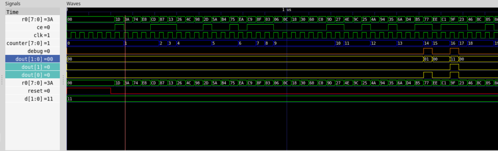
Let’s have a look at a MyHDL code snippet. This is a simple counter, that increments when ce is true (high). When it hits a certain value, the dout output is asserted to a specific value.
When we run a simple test bench which provides a clock signal clk, and some pseudo random assertion of the ce pin, we get this:
Waveform of simulation
Now, how do we pass this simple logic on to yosys for synthesis?
Pyosys python wrapper
The pyosys module is a generated python wrapper, covering almost all functionality from the RTLIL yosys API. In short, it allows us to instanciate a design and hardware modules and add hardware primitives. It’s like wiring up 74xx TTL logic chips, but the abstract and virtual way.
Means, we don’t have to create Verilog or VHDL from Python and run it through the classic yosys passes, we can emit synthesizeable structures directly from the self-parsing HDL.
Way to synthesis
Now, how do we get to synthesizeable hardware, and how can we control it?
We do have a signal representation after running the analysis routines of MyHDL. Like we used to convert to the desired transfer language, we convert to a design, like:
design = yshelper.Design("test_counter")
a = test_counter(clk, ce, reset, dout, debug)
a.convert("verilog")
a.convert("yosys_module", design, name="top", trace=True)
design.display_rtl() # Show dot graph
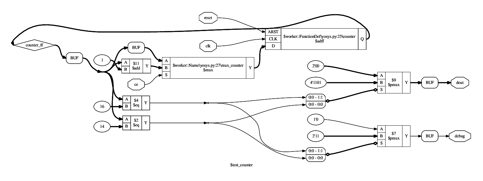
The yosys specific convert function, as of now, calls the pyosys interface to populate a design with logic and translates the pre-analysed MyHDL signals into yosys Wire objects and Signals that are finally needed to create the fully functional chain of the logic zoo. The powerful ‘dot’ output allows us to look at what’s being created from the above counter example (right click on image and choose ‘view’ to see it in full size):
Schematic of synthesis, first output stage
You might recognize the primitives from the hardware description. A compare node if counter == 14 translates directly to the $eq primitive with ID $2. A Data flip flop ($dff) however is generated somewhat implicit by the @always_seq decorator from the output of a multiplexer. And note: This $dff is only emitted, because we have declared the reset signal as synchronous from the top level definition. Otherwise, a specific asynchronous reset $adff would be instanciated.
The multiplexers finally are those nasty omnipresent elements that route signals or represent decisions made upon a state variable, etc.
You can see a $mux instanciated for the reset circuit of the worker() function, appended to another $mux taking the decision for the ce pin whether to keep the counter at its present value or whether to increment it ($11). The $pmux units are parallel editions that cover multiple cases of an input signal. Together with the $eq elements, they actually convert well to a lookup table — the actual basic hardware element of the FPGA.
Hierarchy
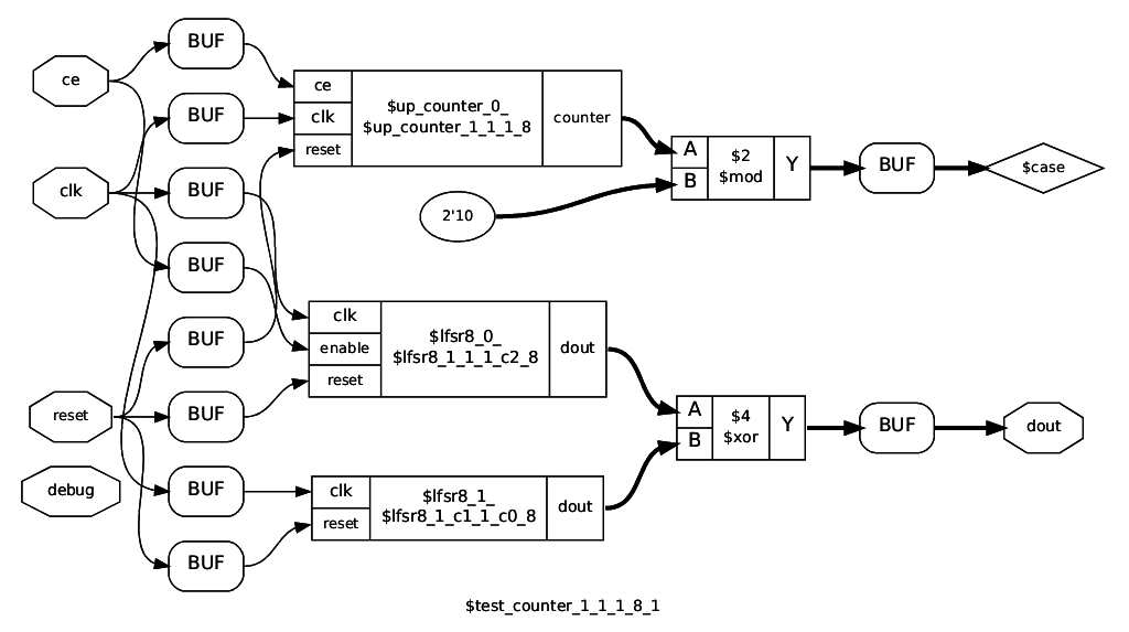
The standard VHDL/Verilog conversion flattens out the entire hierarchy before conversion. This approach avoids this by maintaining a wiring map between current module implementation and the calling parent. Since @block implementations are considered smart and can have arbitrary types of parameters (not just signals), this is tricky: We can not just blindly instance a cell for a module and wire everything up later, as it might be incompatible. So we determine a priori by a ‘signature key’ if a @block instance is compatible to a previous instance of the same implementation.
All unique module keys are thus causing inference of the implementation as a user defined cell. The above dot schematic displays the top level module, instancing a counter and two LFSR8 cells with different startup value and dynamic/static enable.
Black boxes
When instancing black box modules or cells directly from MyHDL, you had to create a wrapper for it, using the ugly vhdl_code or verilog_code attribute hacks. This can be a very tedious process, when you have to infer vendor provided cells. You could also direct this job to the yosys mapper. The following snippet demonstrates an implementation of a black box: the inst instance adds the simulation for this black box, however, the simulation is not synthesized, instead, the @synthesis implementation is applied during synthesis. Note that this can be conditional upon the specified USE_CE in this example.
This also allows to create very thin wrappers using wrapper factories for architecture specific black boxes. In particular, we can also use this mechanism for extended High Level Synthesis (HLS) constructs.
Verification
Now, how would we verify if the synthesized output from the MyHDL snippet works correctly? We could do that using yosys’ formal verification workflow (SymbiYosys), but MyHDL already provides some framework: Co-Simulation from within a python script against a known working reference, like a Verilog simulation.
These verification tests are run automatically upon checkin (continuous integration, see also docker container hackfin/myhdl_testing:yosys)
An overview of the verification methods are given inside the above binder. Note: the myhdl_testing:yosys container is not up to date and is currently used for a first stage container build only.
Functionality embedded in the container:
Functional MyHDL simulation of the unit under test with random stimulation
Generation of Verilog code of the synthesized result
Comparison of the MyHDL model output against the Verilog simulation output by the cycle-synchronous Co-Simulation functionality of MyHDL
There are some advantages to this approach:
We can verify the basic correctness of direct Python HDL to yosys synthesis (provided that we trust yosys and our simulator tools)
We can match against a known good reference of a Verilog simulator (icarus verilog) by emitting Verilog code via MyHDL
Likewise, we can also verify against emitted VHDL code (currently not enabled)
Synthesis for target hardware (ECP5 Versa)
Currently, only a few primitives are supported to get a design synthesized for the Lattice ECP5 architecture, in particular the Versa ECP5 development kit. The following instructions are specific to a Linux docker environment.
First, connect the board to your PC and make sure the permissions are set to access the USB device. Then start the docker container locally as follows:
Then you can synthesize, map, run PnR and download to the target in one go, see the ECP5 specific examples in the playground.
Note: when reconnecting the FPGA board to Power or USB, it may be necessary to restart the container.
Status, further development
MyHDL main development has turned out to have some more serious issues:
Numerous bugs and piling up pull requests
Architectural issues (AST parsing versus execution/generation), problematic internals for hierarchy preservation
Slow execution for complex hierarchies
No closed source modules feasible
From more experiments with a different approach, the roadmap has become clearer such that all yosys related direct synthesis support is migrated to the new ‘v2we’ kernel which provides some MyHDL emulation. For the time being, the strategy is to go back to VHDL transfer and verification using GHDL to make sure the concept is sound and robust. Link to prototype examples:
Automatisches Testen und Verifizieren von Software ist spätestens mit dem Schlagwort “CI” – Continuous Integration zum Standard für grössere Softwareprojekte geworden. Bei aller möglichen Überflutung mit derartigen Reizwörtern darf man hier kurz innehalten und nachfragen: Was ist das genau? Bringt mir das was?
Ein paar Aspekte für den klassischen innovativen Entwickler zusammengefasst:
Man wird älter und kann/will sich nicht mehr alles merken
Man hat beim allgemeinen Preiskampf weniger Zeit für ausführliche Dokumentation
Die Bibliothek oder das Sammelsurium an möglichst (!) wiederverwartbarem Sourcecode ist angewachsen und der kontiuierliche Unterhalt wird immer aufwendiger
Implementiere ich etwas Neues, mache ich vielleicht etwas Altes kaputt
Diverse Technologien zur Virtualisierung von Komponenten (Docker, Virtuelle Maschinen, Linux Container, …) lösen das Problem insofern, dass sich Bausteine aus Projekt A nicht Baustellen aus Projekt (oder gar Problem) B in die Quere kommen (und umgekehrt). Trotzdem möchte man möglichst viele Gemeinsamkeiten abdecken. Also ergibt sich eine klassische NxM-Komplexität: N Bausteine müssen gegen M Konfigurationen/Varianten getestet werden.
Nichts leichter als das: Systeme aus der Opensource-Szene wie Tinderbox oder der Nachfolger buildbot, oder auch teilkommerzielle Dienste wie Travis CI sind beim Testen von Software soweit behilflich, dass für alle Beteiligten, sei es OpenSource oder proprietär/Closed Source, ein Produkt aus der automatisierten Pipeline ploppt, welches – zumindest im Idealfall – gegen eine Menge Fehlerszenarien und Konfigurationen automatisch getestet worden ist.
Test-Szenarien
Gegen was muss denn jetzt typischerweise getestet werden? Nehmen wir an, unsere Software bietet eine Funktionalität einer Bibliothek, d.h. ein Nutzer soll Funktionen aufrufen können. Generell bietet sich der Ansatz einer Bibliothek aus Erfahrung immer an, mit dem Fokus auf:
Wiederverwertbarkeit von Code und Algorithmen
Optimale Interoperabilität
Optimale Abdeckung vieler Anwendungsfälle und Szenarien
Der Aufruf einer Funktion bedingt immer: Eingabe-Daten haben eine mehr oder minder sinnvolle Ausgabe zur Folge, oder gar einen Absturz oder eine Endlos-Schleife. Standard-Strategie ist bei uns, diese Funktionen mit einem virtuellen ‘Adapter’ so zum umwickeln (‘wrappen’), dass sie aus der mächtigen Scriptsprache Python aufgerufen und gegen Szenarien oder Messdaten getestet werden können.
So weit ist das alles mit erträglichem Aufwand für Software implementierbar.
Testen von Hardware
Das Testen von Hardware ist eindeutig kniffliger. Hier lässt sich a priori nicht einfach ein Script schreiben, typischerweise geht es um sogenannte parallel auftretende ‘Test-Vektoren’. Vereinfacht: Angenommen, wir haben einen (virtuellen) Chip, der 16 Eingänge und 16 Ausgänge besitzt. Rhetorische Frage: Kann der Chip mit allen möglichen Eingangssignalen sinnvolle Ausgangssignale erzeugen, so dass alle Zustände definiert sind?
Da die Eingänge unterschiedliche Funktion haben, wie z.B. Takteingänge, reicht eine statische Analyse niemals aus, und die Testszenarien müssen im Grunde genommen immer auf die Funktion der Ein/Ausgänge zurechtgeschnitten werden. Geht auch alles, allerdings mit erheblich höherem Aufwand als für die Software. Wenn alle möglichen Zustände und Sequenzen irgendwie abgefangen werden müssen, um entweder in einem OK oder ERROR-Status zu enden, wird das Problem je nach Komplexität nicht mehr handhabbar, bzw. reicht ein einziger PC nicht dazu aus.
Dazu kommt, dass die Simulationstools, die solche Fehlerszenarien durchspielen können, noch nicht allzulange auf mehreren Rechnern ohne Kostenexplosion verteilbar sind. D.h. für die “Cloud” ist das für den einfachen Anwender oder die Kleinfirma keine legale Option. Es muss also auf OpenSource zurückgegriffen werden, was aber weitere Risiken mit sich bringt: Opensource ist, spätestens nach dem Download, nicht mehr kostenfrei und es gibt – ohne einen vorliegenden Supportvertrag – keine Garantie für gewünschte Funktionalität.
Der Paradigmenwechsel
Wie schon vor vielen Jahren die Gnu Compiler Collection (GCC) teure, proprietäre Compilerlösungen abgelöst hat, und bei allen Unkenrufen zum Trotz die Nummer Eins beim Übersetzen von Sourcecode für andere Architekturen geworden ist, zeichnet sich auch in der Hardware-Welt ein Paradigmenwechsel ab. Wird sind eigentlich an dem Punkt, wo jeder mit entsprechend Know-How in der Lage ist, sich sein eigenes Computerdesign zu entwerfen und es auch zu testen, ohne dass es an Geld für entsprechende Werkzeuge mangelt. Die Übergänge zwischen Software- und Hardware (in der akademischen Welt oft noch klar getrennt) werden fliessender, gefragt sind robuste Lösungen, Gesetzgeber pochen mehr auf Garantie und Haftung — auch bei kleinen innovativ-agilen Entwicklern.
Wie löst sich diese gordische Knoten?
Dazu liesse sich ein Buch schreiben. Aber warum nicht gleiches mit Gleichem vergelten: In der Opensource-Welt hört man schon mal den Spruch: Read the source, Luke.
Also möchte ich schliesslich auf das OpenSource-Konzept ‘MaSoCist’ verweisen, was wiederum auf einem Sammelsurium an existierenden OpenSource-Tools aufbaut, seien genannt:
Der gcc GNU compiler
GHDL – ein OpenSource VHDL Simulator
Linux, GNU Make
… und eine Handvoll Software-Tools aus dem eigenen Hause
Als Sourcecode-Hoster wurde github ausgewählt, so findet sich entsprechend das Code-Repository unter
Der MaSoCist ist im Grunde genommen eine komplexe Anleitung und Regelsammung um Hardware zu bauen. Dazu gehört a priori die Simulation derselbigen. Bei dieser Art der Entwicklung muss man sich dabei auf sehr viele Dinge verlassen, insbesondere darauf, dass:
Die OpenSource-Werkzeuge (die teilweise gebaut werden) korrekt funktionieren
Die Abhängigkeiten von externen Werkzeugen und Bibliotheken stimmen
Das heisst, wir müssen unsere Tools auch laufend gegentesten, denn irgend jemand könnte im Laufe der Entwicklung etwas beschädigen.
So ist der MaSoCist nicht nur ein Baukasten für Hardware, er testet sich zudem selbst, dank einiger Dienste, die die OpenSource-Welt für uns bereitstellt.
Was baue ich jetzt genau mit dem MaSoCist?
Grob lässt sich das wie folgt auflisten:
Es wird ein virtueller (oder auch für FPGA synthetisierbarer) Mikroprozessor gebaut
Es wird die zugehörige Peripherie (UART, I2C, …) gebaut
Es wird die Test-Firmware für eine gewisse Plattform übersetzt und als ROM-Datei in die Simulation integriert
Das Ganze lässt sich wie ein Linux-Kernel konfigurieren, d.h. CPU core, Anzahl und Art der Interfaces lassen sich entsprechend der Möglichkeiten, die die mitgelieferten Style-Sheets bieten, auswählen.
Schliesslich: Die virtuelle Architektur wird mit externen Stimuli per sog. Co-Simulation auf korrekte Funktion getestet
Optional erstellt der MaSoCist auch die komplette Systemdokumentation aller Register, usw. Natürlich muss manuell die passende Dokumentation zum ‘Chip’ erstellt werden.
Simulationsszenarien
Mehrere Ansätze sind hier gängig:
Simulation eines Hardware-Designs ohne CPU gegen externe Software, Daten, oder Stimuli (UART-Eingaben, ..)
Simulation des Gesamtsystems mit der innewohnenden Firmware und CPU, allenfalls ohne externe Stimuli
Der MaSoCist nutzt hierbei die Möglichkeiten, die GHDL bietet, um entweder eine Simulation mit statischen/fixen Testmustern zu stimulieren (wie aus einer VHDL-Testbench heraus) oder die dynamischen Ansätze der Co-Simulation über unsere ghdlex Bibliothek. Hierbei können einfache Kommandozeilenaufrufe oder ein Python-Script die Simulation ansteuern und auf Herz und Nieren (in der Cloud) testen.
Wie beginne ich?
Am besten mit einem Docker Container. Das hat den Vorteil, dass keine Software – ausser allenfalls dem Docker-Dienst oder einer virtuellen Linux-Maschine – installiert werden muss.