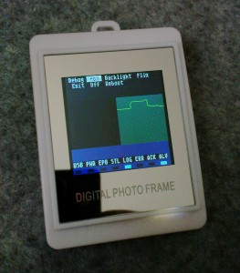
It turned out by some further hacking that we could run a bit more than just patched code bits on these little frames. This is the next step of development, where things are actually getting fun: Running our own firmware on the AX206 chip using the SDCC’s built in bank switching technique.

As seen in the image, we have a little slow scope running, using the built in ADC. It turns out, that this chip is quite good at power saving, once you activate all possible options to turn off various clocks. It can obviously run for weeks with just the real time clock running, waking up the chip every second, then for example doing something every 30 seconds, then putting it back to sleep.
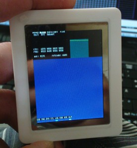
Also, a few extra modes for lcd4linux were explored, like setting backlight intensity and orientation. On the 320×240 frames that are for example available here http://www.pearl.de/a-HPM1184-5618.shtml, we use the display in portrait mode as seen below.

This is not very pleasant to the average user, therefore this solution will need to mature a little before it is actually safe to release.
The full blown framework to build code for the DPFs using SDCC is published here:
https://sourceforge.net/projects/dpf-ax/
SVN access to the sources:
svn co https://dpf-ax.svn.sourceforge.net/svnroot/dpf-ax/trunk dpf-ax
UPDATE: The bootloading protocol is now decoded. Code can be loaded on bricked frames, find a flash update tool in the above repository. A brief intro how it works:
When the DPF goes into Bootloader mode (showing USB ID 1908:3318), it expects max. 64 byte size USB interrupt messages with a header and payload data. The header implements a simple Remote Procedure Call format through the bootload handler. Its format is as follows:
typedef struct {
	unsigned char len;
	unsigned char chk;
	unsigned char jmp[2];
	union {
		// Structures for various backends
		// The default memory loader:
		struct {
			unsigned char offset[2];
			unsigned char buf[BUFSIZE];
		} loader;
		struct {
			unsigned char opcode;
			unsigned char n;
			unsigned char buf[16];
		} spi;
	} u;
} UsbMsg;
Description
The ‘len’ byte specifies the full length of the USB packet. ‘chk’ is a checksum that is consecutively updated with every packet sent. The ‘jmp’ field contains the jump address of the handler that takes care of the attached data payload. For simple memory writing, the address of the internal ROM memory write routine is used. Once a program (for example flashing routines) is loaded into memory, it can be jumped into using this RPC scheme.
