Posted on Leave a comment

Lossless prediction coding vs. Wavelet

General method

For the encoding pipeline, a pretty much standard approach is used for either lossless (up to 12 bit grayscale) or quantized (lossy) encoding.

Both lossy and lossfree pipelines use a high speed huffman encoder with different code books and up to four contexts.

In the lossy mode, the image is decomposed into AC and DC subbands using a standard DWT approach. However, a predictor (called ‘sliding T’), different from JPEG2000 or JPEG LS is used and the special treatment is done by a particular bit plane shuffling. This makes the encoding logic much easier and allows to optimize the huffman tables in some cases ‘on the fly’.

Lossless mode

In lossless compression mode, it has turned out that the AC/DC subband decomposition does not beat the ‘Sliding T’ predictor in most cases. This observation comes close to statistics done on Lossless JPEG (not JPEG LS). The Sliding T Predictor (so forth STP) is context sensitive and is aware of up to 27 contexts, however in many cases only eight (‘STP8’) are used.
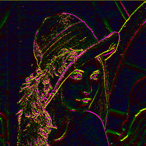
Example

Here’s a visualization of the prediction step: The prediction image, generated via a lookup table, depicts the deviations from the differential coding using the STP8.


Prediction error image

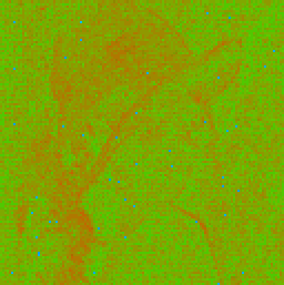
How well the compression performs, is seen in the so called ‘penalty map’. A very good compression (low entropy) can occur in the green areas, the more heading towards red, the more bits in the variable bit encoding are needed.

Penalty map (green: optimum compression, red: high entropy)

Lossy mode

In lossy mode, a quantization steps occurs inside the predictor loop (to eliminate errors) as well as a small optional quantization on the source data.

This introduces artefacts and may create quantization noise known from classical DPCM methods, although the predictor is not considered linear, but dependent from its pixel processing history (which is stored in a back log). The critical thing is to make sure the back log on encoder and decoder is the same.

This quantization step can occur both on AC and DC subbands, however for optimum compression, the 27 state ‘STP27’ was introduced to take care of special characteristics found in the AC subbands (‘HL’, ‘LH’, ‘HH’).

The interesting thing in the image below is that the artefacts at level 1 decomposition introduce too much entropy when using STP8 on the HH image. Very likely these are artefacts from repeated re-coding of the famous Lena image (although an assumed lossless PNG source was used).

The level 2 subband images depict how a quantized prediction reduces entropy such that a signification compression gain is achieved.

However, the STM8 lossless predictor performs better in this case than a lossless (reversible) DC/AC re-composition.

HH level 1 subband penalty map
HH level 2
HH level 2, quantized/predicted
Lena gray scale output, (lossy compression < 1:50, raw payload: 1:74)
Lena ‘original’ PNG

Wrap up

Compared to JPEG2000 with way much higher complexity, this approach performs less efficient on many high quality images, however it comes pretty close on a number of test images. For a particular application where the source data is correlated (e.g. Bayer Pattern), the STP8 performs quite well in lossless mode and does not require a complex hardware pipeline.

Lossy mode however takes some more complexity and only performs well with increasing quantization on AC/DC subbands. Depending on the quantization mode, either memory for lookup tables or DSP units for multiplication are required in the hardware pipeline.

Open items:

  • Detailed statistics (being collected)
  • Bit rate control (truncation mode)
  • 16 bit grayscale: Not yet implemented
  • NHW codec compatibility: Introduce YCoCg, Predictor?
Posted on Leave a comment

NHW codec tests

Original PNGs

LOW8 quantization

LOW19 quantization

Posted on Leave a comment

Lattice VIP MJPEG streaming

The EVDK or VIP from Lattice Semiconductor (Embedded Vision Development Kit) is a stereo camera reference design for development of machine vision or surveillance applications. It is based on a ECP5 FPGA as main processing unit and a CrossLink (LIF-MD6000) for sensor interface conversion. As an add-on, a GigE and USB vision capable output board can be purchased and is required for this demo.

The image acquisition board of the VIP is equipped with two rolling shutter sensors IMX214 from Sony. Unfortunately, their register map is not publicly available. The on board CrossLink unit translates video data coming through two MIPI interfaces into a parallel video stream which is easier to handle by the processor board. There are two different default firmware images for the CrossLink:

  1. Stereo mode: both sensor’s images are merged at half the x resolution (cropped)
  2. Mono mode: Only image data coming from Sensor CN2 is forwarded

The CrossLink bit files are available at Lattice Semi after registration [ Link ]

The MJPEG streaming bit file is available for free [ MJPEG-Streaming-Bitfile-for-VIP ].

JPEG-Streaming

As reference receiver for the JPEG RFC2435 stream we use the gstreamer pipeline framework. Create a script as follows:

caps="application/x-rtp, media=\(string\)video,"
caps="$caps clock-rate=\(int\)90000,"
caps="$caps encoding-name=\(string\)JPEG"

gst-launch-1.0 -v udpsrc \
caps="$caps" \
port=2020 \
! rtpjpegdepay \
! jpegdec \
! autovideosink

When calling this script under Linux (as well as under Windows) gstreamer runs a RTP MJPEG decoding pipeline and displays the video strom as soon as it arrives. The stream must then be configured on the VIP.

Stream configuration

  1. Connect USB programmer cable to VIP processor board. Then start a terminal (like minicom) with serial parameters 115200 bps, 8N1
  2. Connect to /dev/ttyUSB1 (Linux) or the corresponding virtual COM port on Windows
  3. Load ECP5 MJPEG encoder reference design (bit file) onto the target using the Diamond Programmer
  4. On the console, configure address of receiver:
    r 192.168.0.2
  5. Verify ARP reply:
    # Got ARP reply: 44 ac de ad be ef
  6. Start JPEG-Video, e.g. 1920×1080 @ 12fps (slow bit rate):
    j 2

If the JPEG stream stops, the reason is mostly a bottleneck in encoding. Under certain circumstances, FIFO overflows can be provoked by holding a colorful cloth in front of the camera. Also, a fully white saturation may fill up the FIFOs in this demo. The JPEG encoder is configured to allow up to five overflows before terminating the stream. For detailed error analysis, see documentation of MJPEG Encoder.

Sensor parameter configuration

The connected sensors are configured via the i2c bus:

# scan i2c-Bus (only when JPEG stream off):

i

# i2c register query (hexadecimal values):

i 100

# set i2c register:

i 100 1

Simplified sensor access (also, values are in hexadecimal notation):

Function

Command
se [Value] Exposure
sh [0|1] HDR mode
sr [Gain] Gain red
sg [Gain] Gain green
sb [Gain] Gain blue

Examples

These are JPEG images captured from the encoded stream without further conversion. They use the Crosslink firmware for stereo sensor configuration. Image errors can occur due to probable synchronization issues at a lower pixel clock.

Stereo test image (‘j 4’ command)
Broken stereo image (MIPI output frequency too low)

General Troubleshooting

  • Video does not start:
    1. Check error messages on console. If ‘Frames received’ upon video stop (‘j’) shows 0, the sensor configuration may be incorrect or the CrossLink is not properly initialized.
    2. Check for Network activity (orange LED) on GigE board
    3. Use wireshark to monitor network activity
  • Video starts, but terminates:
    1. Check error bits on console: [DEMUX], [FIFO], …
    2. Increase quantisation value (better compression):
      q 30
    3. Check for lost packets with wireshark
    4. Try direct network connection between VIP and PC (no intermediate router)
  • Broken images:
    1. Check again for error bits on console. It is also possible, that the CrossLink reference design does not properly handle the clock coming from the sensor.