The EVDK or VIP from Lattice Semiconductor (Embedded Vision Development Kit) is a stereo camera reference design for development of machine vision or surveillance applications. It is based on a ECP5 FPGA as main processing unit and a CrossLink (LIF-MD6000) for sensor interface conversion. As an add-on, a GigE and USB vision capable output board can be purchased and is required for this demo.
The image acquisition board of the VIP is equipped with two rolling shutter sensors IMX214 from Sony. Unfortunately, their register map is not publicly available. The on board CrossLink unit translates video data coming through two MIPI interfaces into a parallel video stream which is easier to handle by the processor board. There are two different default firmware images for the CrossLink:
- Stereo mode: both sensor’s images are merged at half the x resolution (cropped)
- Mono mode: Only image data coming from Sensor CN2 is forwarded
The CrossLink bit files are available at Lattice Semi after registration [ Link ]
The MJPEG streaming bit file is available for free [ MJPEG-Streaming-Bitfile-for-VIP ].
JPEG-Streaming
As reference receiver for the JPEG RFC2435 stream we use the gstreamer pipeline framework. Create a script as follows:
caps="application/x-rtp, media=\(string\)video,"
caps="$caps clock-rate=\(int\)90000,"
caps="$caps encoding-name=\(string\)JPEG"

gst-launch-1.0 -v udpsrc \
caps="$caps" \
port=2020 \
! rtpjpegdepay \
! jpegdec \
! autovideosink
When calling this script under Linux (as well as under Windows) gstreamer runs a RTP MJPEG decoding pipeline and displays the video strom as soon as it arrives. The stream must then be configured on the VIP.
Stream configuration
- Connect USB programmer cable to VIP processor board. Then start a terminal (like minicom) with serial parameters 115200 bps, 8N1
- Connect to /dev/ttyUSB1 (Linux) or the corresponding virtual COM port on Windows
- Load ECP5 MJPEG encoder reference design (bit file) onto the target using the Diamond Programmer
- On the console, configure address of receiver:
r 192.168.0.2
- Verify ARP reply:
# Got ARP reply: 44 ac de ad be ef
- Start JPEG-Video, e.g. 1920×1080 @ 12fps (slow bit rate):
j 2
If the JPEG stream stops, the reason is mostly a bottleneck in encoding. Under certain circumstances, FIFO overflows can be provoked by holding a colorful cloth in front of the camera. Also, a fully white saturation may fill up the FIFOs in this demo. The JPEG encoder is configured to allow up to five overflows before terminating the stream. For detailed error analysis, see documentation of MJPEG Encoder.
Sensor parameter configuration
The connected sensors are configured via the i2c bus:
# scan i2c-Bus (only when JPEG stream off):
i
# i2c register query (hexadecimal values):
i 100
# set i2c register:
i 100 1
Simplified sensor access (also, values are in hexadecimal notation):
Function
| Command | |
|---|---|
| se [Value] | Exposure |
| sh [0|1] | HDR mode |
| sr [Gain] | Gain red |
| sg [Gain] | Gain green |
| sb [Gain] | Gain blue |
Examples
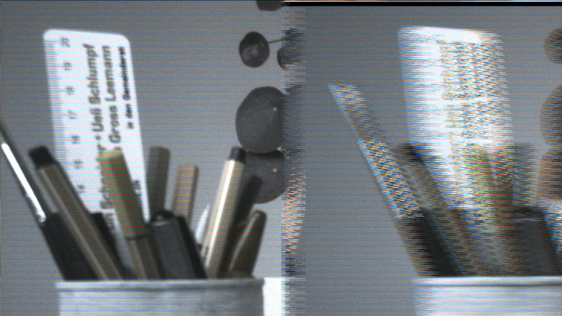
These are JPEG images captured from the encoded stream without further conversion. They use the Crosslink firmware for stereo sensor configuration. Image errors can occur due to probable synchronization issues at a lower pixel clock.

General Troubleshooting
- Video does not start:
- Check error messages on console. If ‘Frames received’ upon video stop (‘j’) shows 0, the sensor configuration may be incorrect or the CrossLink is not properly initialized.
- Check for Network activity (orange LED) on GigE board
- Use wireshark to monitor network activity
- Video starts, but terminates:
- Check error bits on console: [DEMUX], [FIFO], …
- Increase quantisation value (better compression):
q 30
- Check for lost packets with wireshark
- Try direct network connection between VIP and PC (no intermediate router)
- Broken images:
- Check again for error bits on console. It is also possible, that the CrossLink reference design does not properly handle the clock coming from the sensor.