netpp node [Spartan6-LX9]
I am glad to announce a new user evaluation platform module called ‘netpp node’. Its motto is ‘IoT on FPGA done right’. See detailed specs and preliminary order information here: [ refdesigns/netpp_node ].
Update [21.12.]:
The netpp node engineering samples v0.0 have just passed the long term burn-in. Running since approx. 11 weeks non-stop, the units are flooded with netpp requests from an embedded PC and have shown no failure in the hardware, except a reboot resulting from a power outage.
v0.1 series [18.1]:
Received the series! So finally we can ramp up with the delivery to beta developers…(thanks for being so patient).
Analog I/O
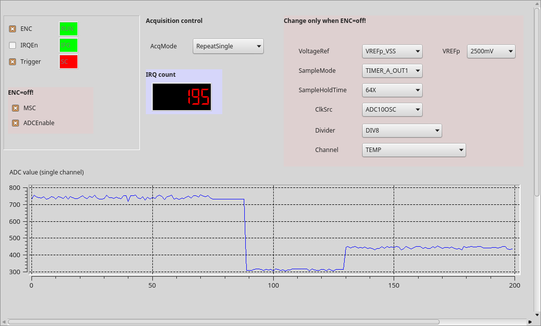
For analog I/O, U3 on the board is by default populated with a MSP430G2553, functioning as a smart ADC that is controlled from the ZPUng ‘dagobert’ SoC via i2c. All relevant ADC configuration registers are directly accessible via netpp. For instance, we access the low level registers through a process browser panel as shown above to play with the parameters. The process view panel automatically updates the volatile properties from the netpp peer device. The ADC10 variant of the netpp node provides up to six analog channels internally sampled at up to 200ksps. When in synchronous acquisition configuration (SPI master), only five channels can be used.
Differential 16 bit sigma-delta ADC
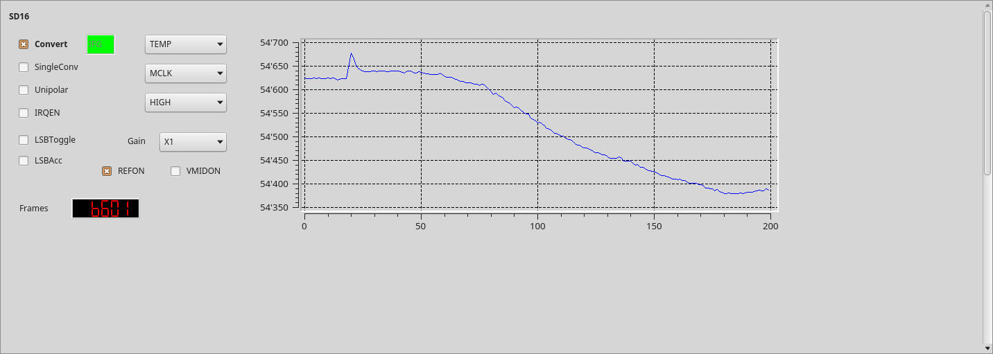
The alternate population option with a MSP430F2013 provides a Sigma-Delta 16 bit ADC with differential inputs and programmable gain amplifier. This variant provides three different input channel configurations using the provided analog input pins on this board. Moreover, the internal temperature is available in a separate channel.
‘Push on demand’ data streaming
By default, the analog sensors are polled, i.e. a measurement value is delivered upon request by the master. For synchronous sampling however, a ‘push’ strategy might be desired, where a netpp node delivers a value stream to a data logger or database. This can be netpp (where the netpp node acts as a master), however for high speed data transfers (‘network scope’), a low overhead UDP stream is more desirable. The dagobert SoC features a data port option with programmable slots to stream I/O channels as well as analog values using a standard real time protocol with 90 kHz time stamps.
Monitoring netpp packet performance
Packet behaviour in a real network is measured using the Wireshark protocol analyzer.
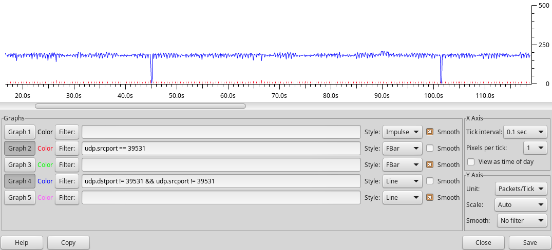
The figure below shows some example netpp transaction log that the netpp node handles at a very low CPU overhead based on direct register accesses.The red bars is the effective number of query responses using somewhat ineffective ping-pong requests. The performance can be increased by accumulating data into larger buffer properties.
For i2c or SPI transactions however, the packet rate is expected way lower.
For high speed performance like MJPEG video streaming, a separate UDP/RTP queue can be set up within the firmware to reach maximum throughput. However, there is no handshaking using this method.
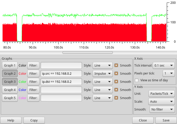
The image below shows a repeated property query from within Python. The pauses are introduced by external disturbance (stress test) that causes a packet drop – and the netpp engine to timeout and re-synchronize.
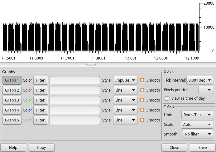
Improved RX/TX queue
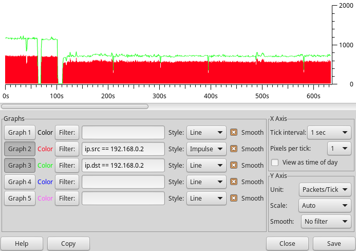
With an improved packet FIFO on FPGA, I was able to crank up the number of netpp requests per second, as shown in the Wireshark trace below. This test makes sure that several netpp clients can poll the netpp node at high frequencies without disturbing each other. The blue trace is a repeated poll of the full property tree, the red bars are the timed queries from a process viewer daemon. With no other disturbance, we get the occasional drops (e.g. at 45s, 101.5s) due to the queue running full
In-Field/System update
The default boot loader firmware supports self-programming over the cable. That means, the netpp_node can be supplied remotely with a new firmware image via a simple upgrade procedure over netpp. If the uploaded image is faulty, the system will fall back to the default boot loader. However, if the new design itself has errors, the system will be unable to recover unless the reset button is pressed.
Test procedures
As the full model of this design is available for simulation, we can verify the system effectively against stress situations. In particular, network safety is of outmost importance. The test procedure check list of the dagobert SoC:
Completed
- ARP and ping flooding
- netpp packet performance test
- Broken packet handling
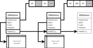
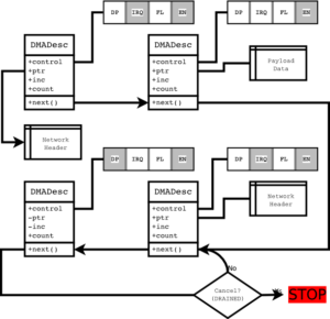
- Lost interrupt scenario (packet queue desynchronization)
Yet open
- Jumbo packet flooding was tested, however support can not be enabled on this platform for the receiver queue. It is however possible under certain circumstances to generate (TX) Jumbo packets for experimental purposes. The performance gain is however minimal.
Extended RTOS support
Currently, the netpp node runs a simply bare metal main loop without particular RTOS functionality, i.e. all user code must be designed such that there are no blocking wait statements. Let me just put the FAQ together:
- There is FreeRTOS and eCos support code for the ZPU architecture. However, I have no plans in going down that road, you’d be on your own.
- A NuttX port is currently under evaluation and may likely be released in a few months time. NO PROMISES!
- A simple ‘netpp OS’ with very basic task management is in experimental stage:
- Guaranteed latency time from driver interrupt to queue handler task
- ‘User space’ context switch when sleep() called
- Very cheap context switches due to ZPU architecture improvements
Code size is an issue on this particular platform, larger programs (TCP stacks) need to move to the SPI flash overlay program space. Since this involves caching, the program timing is no longer fully deterministic and the RTOS functionality can only apply to program code running in the L1 memory.