Posted on Leave a comment

VHDL to XML to …whatever

Time to write about some academic fun again. Well, it’s language stuff you might not think about. Like: What does Python have to do with FPGAs, or VHDL with XML.

If you have been picking up a few bits on this website in the past, you might have learned about the IP-XACT alike approach: Turn XML into HDL using a XSLT style sheet. Things like these are done on the web daily for XML to web pages.

Now we go the other way: Turning VHDL into XML and then turn this into something else again. Why would we want to do that? Let’s save the clue for later and assume there’s this adacemic fun thing only. But what’s the occasion?
Recent versions of the free GHDL VHDL compiler and simulator were augmented by a –file-to-xml option, which dumps the fully analyzed AST (abstract syntax tree) into an XML structure. Typically, this results in a huge file, including lots of cross references between analyzed objects, representing all of the complexity of carefully engineered languages as VHDL.

But why would we want to go beyond something that is as strict as VHDL?

Users familiar with GHDL might not just like it for its simulation purposes, but also for its excellent analysis and re-factoring features, such as the cross referenced HTML output. The XML file output option is taking this even further: Now you can basically analyze your code structures even more in depth and your own customized way, without getting into the VHDL parsing yourself.
But…halt. What’s taking the burden from parsing XML instead of VHDL? That’s where the XSLT technology comes in. We don’t have to mess with all tree related issues in a programming language. XSLT might be unreadable and not too easy to debug, but once you get the hang of it, it can save you a lot of work. More plusses:

  • It’s compact
  • It allows to switch between  ‘lazy analysis’ and ‘complex coverage’ approach using its template features
  • It runs in a browser

The last item is represented in a demo below.

So where is this heading? This XML discussion might have been originated from some pondering on how to get from VHDL analysis (done by GHDL) to a synthesizable net list, or anything that can be fed to a mapper.
That’s ambitious, really. But why not take the small steps first:

  • Create a graph from an entity [Demo]
  • Check HDL for non-synthesizable constructs
  • Check HDL for design rules
  • Convert HDL into [ MyHDL, Verilog, …]
  • Create language independent RTL format for OpenSource mappers
  • Follow whygee’s idea of a smart elaboration towards synthesis
Posted on Leave a comment

Unlocking USB sticks from Ubuntu/Linux

Just recently, I bought a USB stick from a major discounter. When sticking it in, it showed some preinstalled software to configure a hidden partition. Ok, nice feature, when you lose your stick.

Let’s have a look at the outlines:

Bus 002 Device 035: ID 13fe:3623 Kingston Technology Company Inc.

It is branded as a Maxell pen drive.

I will not go into the security details, but take my advice and don’t assume your data is well encrypted or really secure. An electronics Pro will be able to read out your data!

Anyhow, so I have my hidden partition, but I’d like to see it from Linux, too (why would I use anything else, ha ha). Bummer, no Linux support. Not giving up early though. We know that a USB drive is in fact a SCSI disk, so it is all about sending the right vendor extension SCSI commands to the right target.

In Linux, this is simply done accessing a scsi generic device. Before losing any more words, here is the C source for it:

Kingston USB memory unlocker source code

You have to compile this utility yourself (do not ask for binaries, or you’ll be pushed with a soft cushion) and run it using sudo or as root (both potentially dangerous) and enter the correct password (when prompted with “Phrase:”) that you have entered when configuring the device under Windows. I’m afraid, no support for setting up the partitions and protection under Linux.

If the password is correct, the drive will reconnect automatically and show up in your file manager.

The Windows Lock tool will give you only a number of limited attempts trying to guess the password before the hidden partition is erased. It has not been tested whether this is a hardware feature or done by the software tool. Comments welcome.

Big fat WARNING: This is an experimental tool. Make sure you do *not* access your hard disk!

To determine the generic SCSI device, see the ‘dmesg’ output after sticking in the USB pen drive. My code above will do a check for the drive ID string, but this might not be paranoid enough.


Posted on 1 Comment

A full baseline pipelined JPEG encoder in VHDL

As described in a previous post, a framework was built to loop in a DCT hardware design into a software JPEG encoder for verification (and acceleration) purposes.

Turns out this strategy speeds up development a lot, and that the remaining modules on the way to a full hardware based and pipelined JPEG encoding solution weren’t a big job. Actually, I was expecting that this enhanced encoder would no longer fit into a small Spartan3E 250k. Wrong!

Have a look:

Device utilization summary:
---------------------------

Selected Device : 3s250evq100-5 

 Number of Slices:                     1567  out of   2448    64%  
 Number of Slice Flip Flops:           1063  out of   4896    21%  
 Number of 4 input LUTs:               2915  out of   4896    59%  
    Number used as logic:              2900
    Number used as Shift registers:      15
 Number of IOs:                          49
 Number of bonded IOBs:                  47  out of     66    71%  
 Number of BRAMs:                        12  out of     12   100%  
 Number of MULT18X18SIOs:                11  out of     12    91%  
 Number of GCLKs:                         2  out of     24     8%

JPEG encoder latency and timing

From the XST summary, we get:

Timing Summary:
---------------
Speed Grade: -5

   Minimum period: 13.449ns (Maximum Frequency: 74.353MHz)
   Minimum input arrival time before clock: 9.229ns
   Maximum output required time after clock: 6.532ns
   Maximum combinational path delay: 7.693ns

The timing is again optimistic, place and route normally deteriorates the latencies. The maximum clock is in fact the clock you can feed the JPEG encoder with pixel data (12 bit) without causing overflow. The output is a huffman coded byte stream that is typically embedded into a JFIF structure header, table data and the appropriate markers by a CPU.

There is quite some room for optimization, in fact, the best compromise of BRAM bandwidth and area has not yet been reached. Quite a few BRAMs ports are not used, but kept open to allow access through an external CPU, like for manipulation of the Huffman tables.

JPEG encoder waveforms

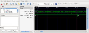
The last performance question might be the latency: how long does it take until encoded JPEG data appears after the first arriving pixel data? The above waveform snapshot should speak for itself: at 50MHz input clock, the latency is approx. 4 microseconds.

Colour encoding

We haven’t talked about colour yet. This is a complex subject, because there are many possibilities of encoding colour, but not really for the JPEG encoder. This is rather a matter of I/O sequencing and the proper colour conversion. As you might remember, a JPEG encoder does not encode three RGB channels, but in YUV space, which might be roughly described as: brightness, redness and blueness. The ‘greenness’ is implicitely included in this information. But why repeat what’s already nicely described: You find all the details right here on Wikipedia.

So, to encode all the colour, we just need properly separated data according to one of the interleaving schemes (4:2:0 or 4:2:2) and feed the MCU blocks of 8×8 pixels through the encoder while assserting the channel value (Y, Cb, Cr) on the channel_select input. Voilà.

Turns out that the Bayer Pattern that we receive from many optical colour sensors can be converted rather directly into YUV 4:2:0 space using the right setting four our Scatter-Gather unit (‘cottonpickens’ engine). With a tiny bit of software intervention through a soft core, we finally cover the entire colour processing stream. Proof below.

Colour JPEG
Colour JPEG output from the encoder
The original RGB photo

As you can see, the colours are quite not perfect yet compared with the original. This is a typical problem, that you get a greenish tint. We leave this to the colour optimization department 🙂

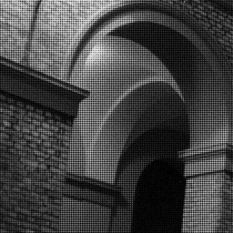
One more serious word: Just yesterday I’ve read the news and had to see that the person who changed the optical colour sensor industry, Bryce Bayer, has passed away. As a final “thank you” to his work, I’d like to post the Bayer Picture of the above.

Bayer pattern source image
Dedicated to Bryce Bayer