The leanXcam has been out for a while now, finally I got my hands on a OEM module.
The first impressions:
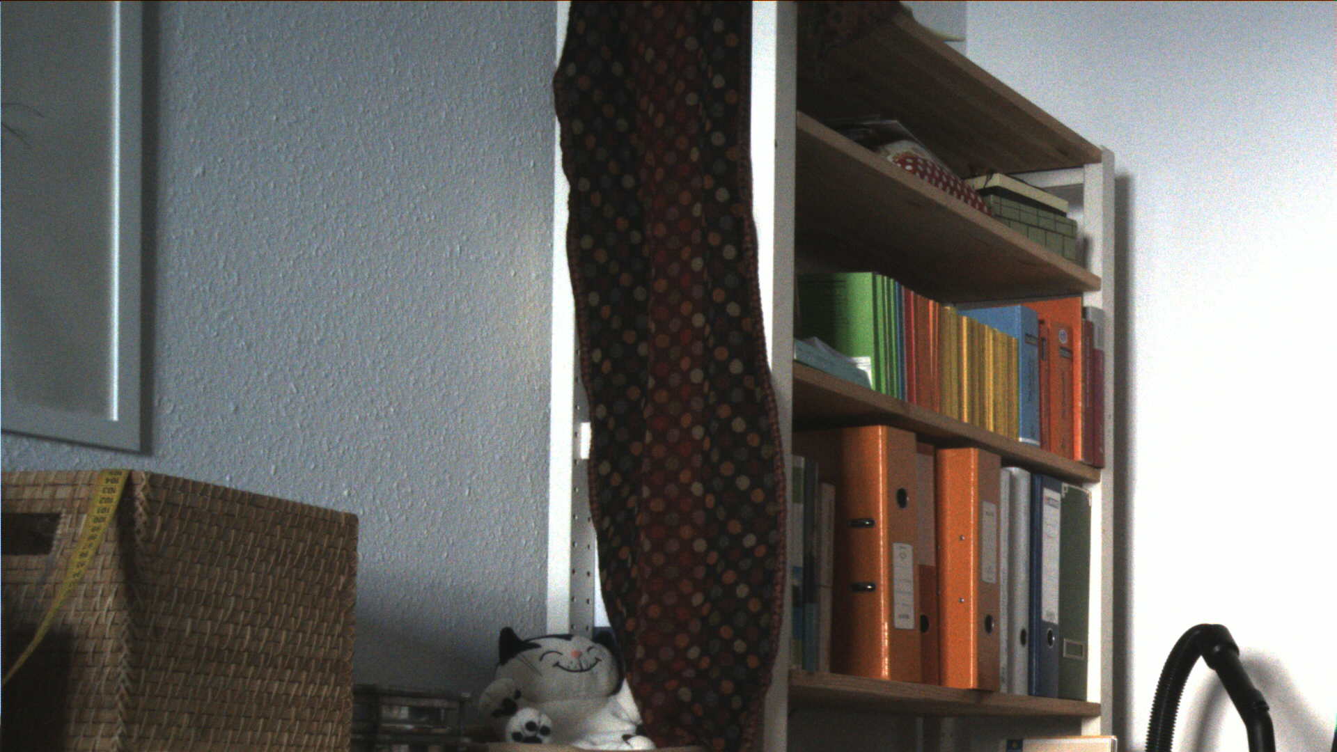
- Interesting 4 plane layout. The bypass caps are somewhat far away from the processor on the top side. Not sure if they are really useful that way..
- Cheap optics, but they do the job
- Plugging in Ethernet and Power, I was able to telnet into the beast at the default 192.168.1.10 within seconds and try the webserver. Nice!
Now, how to run our standalone netpp framework:
The JTAG (which we definitely need for bare metal, i.e. non uClinux development) wasn’t populated. The helpful folks at Supercomputing systems told me the specs of the somewhat unusual SMD header:
Farnell, Order #1421678
Keep in mind that pin 3 must be spare for the key.
So, after being set with JTAG, I plugged in one of the new ICEbearPlus units and run the flashloader:
flashload --info --driver=spi_flash.dxe
This is what we get:
Detected Device: BF-537(536) rev:3
Manufacturer        : Atmel
Device Type         : Dataflash 45DB321D
-------------------------------------------------------------------
 Driver title: SPI flash programmer (STM, Atmel)
 Description: AT45DB321D
 Manufacturer Code: 0x1f
 Device Code: 0x27
 Number of sectors: 0x41
 Number of regions: 0x3
 Bus width: 0x8
 Buffer size: 0x2000
 Flash size: 0x400000
-------------------------------------------------------------------
Cool, that worked from the spot. There is another flash on SPI select 5, i.e. found by flashloader via the –unit=4 option. Before starting to hack, it might be a good idea to save the flash images:
flashload --info --driver=spi_flash.dxe --unit=0 --dump leanx_0.img --size=0x400000
Downloading code
So now. We got this standalone shell code to try out stuff, lets see how the code from the pretty similar STAMP BF537 board can be ported. After a few modifications later, I seem to be able to talk to the shell via the bfpeek console (the bfpeek channel is a way to do stream I/O over JTAG without the need to attach a serial cable):
strubi@gmuhl:~/src/blackfin/shell/boards/LEANXCAM$ nc localhost 4000

/////////////////////////////////////////////////////////
// test shell // (c) 2004-2009, <hackfin-ät-section5.ch>  //
/////////////////////////////////////////////////////////

Board: LeanXcam BF537
>
Let’s see if we see something on the i2c bus:
> i
Detecting devices: 5c
done.
Right, that should be the i2c address of the MT9V032 sensor.
Let’s try grabbing a frame with the ‘v’ command – oops, timeout! Could it be that the sensor is in standby mode? I guess we’ll have to check the schematics now. And here we should emphasize: The leanXcam does not make a secret about its internals: The schematics are openly available (Why keep something a secret that isn’t really one?)
Nah, everything ok, the sensor should run. Giving it a few tries and running into the usual obscure core faults we remember: Random core faults mostly got to do with bad SDRAM! After revisiting the settings and fixing them, we see:
> v 3
Initializing video with 640x480
Video start
Process frame [0], 0 jiffies
Data error in frame 0
Process frame [1], 21 jiffies
Data error in frame 1
Process frame [0], 21 jiffies
Data error in frame 0
Video stop (9 frames received)
 (6 overrun)
Bingo. We lost 6 frames due to the output via the bfpeek channel that burns many CPU cycles, but that was to expect. We ignore the data error, because we didn’t yet enable the test pattern.
Well, this is kinda amazing. It does not happen so often that you plug in hardware of that sort and it works that smooth right away.
Thus, I can recommend the leanXcam to anyone who wants to get into serious image processing, be it uClinux or standalone.