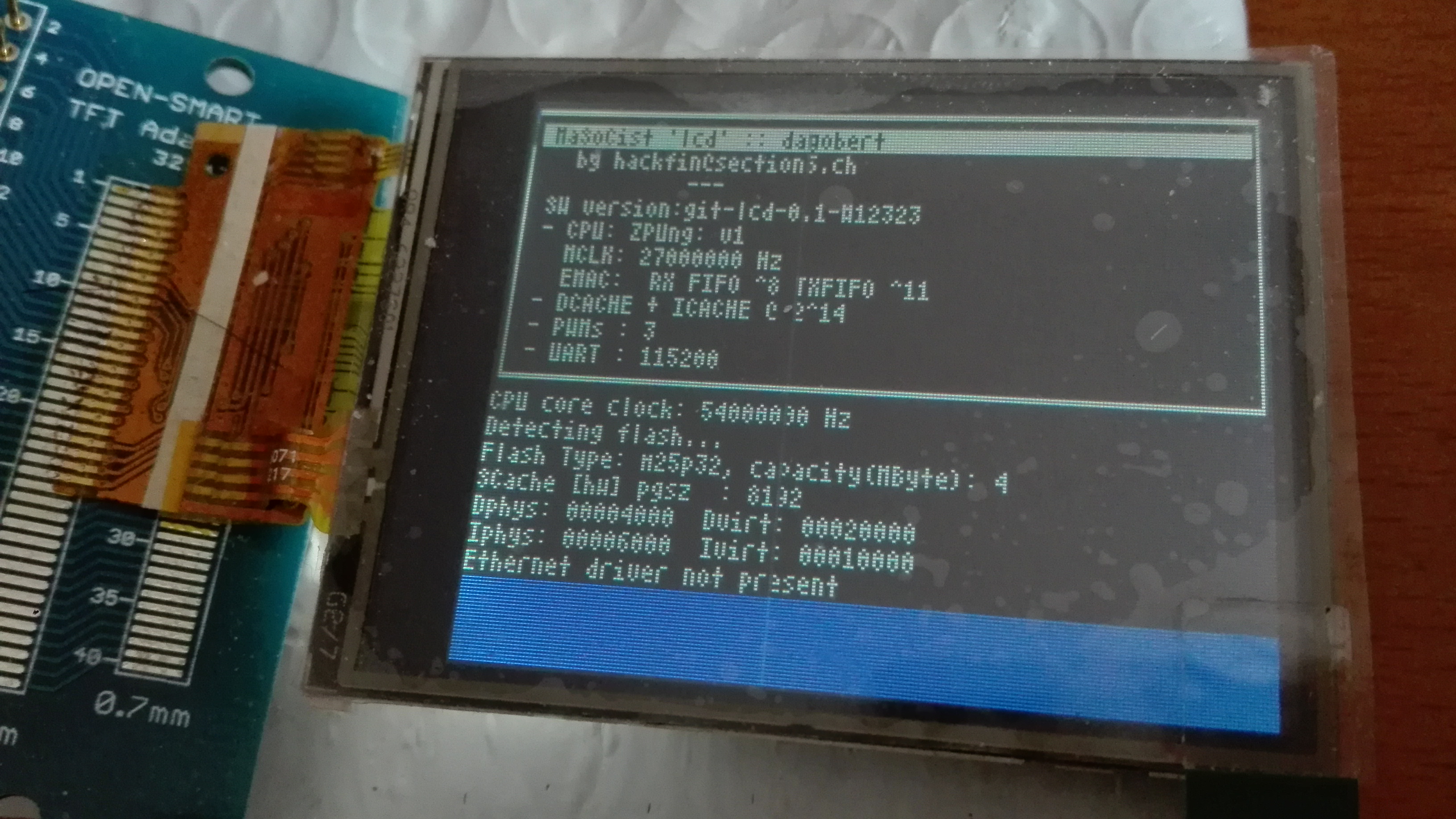
Just as proof of concept, I up-ported the LCD-interface from the ‘beatrix’ SoC to the ‘dagobert’ netpp node default SoC configuration. This also introduces GPIO multiplexing options on port A, meaning, that a few pins have dedicated funcionality driven by an asynchronous bus engine with some extra decompression logic, tailored specifically for LCD screens. Since direct GPIO bit banging would burn a few more cycles and be slow, having a special interface definitely pays off (apart from DMA features, etc.)
The display controller of this OpenSmart variant has different addressing modes, so you can switch between landscape and portrait. However, there’s a catch: When trying to make use of the built-in scrolling feature, it turns out it is only supported for portrait mode, i.e. the shown landscape orientation would require to buffer the terminal content and redraw for each new line.
I have also tried to run a simple GUI toolkit as Achim Döblers µGUI. Due to its simple pixel-wise drawing API it is not very fast, but works ok for most purposes.
What is left to do is the touch screen implementation. This will only work on the ADC10 variant of the netpp node with populated msp430g2553. For now, touch screen is not required, so this task is not scheduled (no pun intended).
Other than that, the same techniques as mentioned in this post are used to save RAM resources using the SCACHE peripheral.
You might save this script to a file like run.sh and start it next time from the Docker Quickstart terminal:
. run.sh
Depending on the MaSoCist release you’ve got, there are different install methods:
Opensource github
See README.md for most up to date build notes. GTKwave is not installed by default. Run
sudo apt-get update gtkwave
to install it.
When you have X support enabled, you can, after building a virtual board, run
make -C sim run
from the MaSoCist directory to start the interactive wave display simulation. If the board uses the virtual UART, you can now also connect to /tmp/virtualcom using minicom.
Custom ‘vendor’ license
You should have received a vendor-<YOUR_ORGANIZATION>.pdf for detailed setup notes, see ‘Quick start’ section.
A few more notes
All changes you will make to this docker container are void on exit. If this is not desired, remove the ‘–rm’ option and use the ‘docker ps -a’ and ‘docker start -i <container_id>’ commands to reenter your container. Consult the Docker documentation for details.
Closing the GTKwave window will not stop the simulation!
Ctrl-C on the console stops the simulation, but does not close the wave window
The UART output of the virtual SoC is printed on the console (“Hello!”). Virtual UART input is not supported on this system, but can be implemented using tools supporting virtual COM ports and Windows pipes.
Once you have the Docker container imported, you can alternatively use the Kitematic GUI and apply the above options, in particular:
For high speed DMA throughput where you’d want the least interruptions, several CPU cores on the higher end deploy scatter-gather style DMA engines to avoid slow memory copying. Let me give an example:
Assume you would want to compose a network package and stream it out to a media access controller IP core (MAC)
You have one Ethernet/IP/UDP/RTP header or alike and you are not planning to change it much during a streaming session
Your payload might be in memory, but also coming from an external data port (such as a video data)
DMA descriptor scheme
The DMAA core (part of the cCAP families starting with ‘d’, like dombert) allows to set up descriptors in a special shared (and fast) dual port memory such that the DMAA engine can stream almost continuously to a peripheral. Likewise, descriptors can be set up for input streams (peripheral to memory), if required. The above image should talk. You start the DMA engine by writing the descriptor address into the DMAA_START_DESC register. Once the transaction has completed, an IRQ will be fired (which will for example allow you to update the sequence number of an RTP packet). Meanwhile, the DMAA engine will fetch the NEXT descriptor pointer (next()) and stream the payload data pointed to by ptr. You just have to make sure the IRQ routine does not waste too much time doing other things, if you use the same header in the following packet.
Note the control bits: an IRQ will for example only be fired, when the according IRQ bit is set. The EN bit tells the DMA engine to keep going after the current descriptor. The entire transaction stops when the last descriptor has the EN bit set to 0.
In the example for a MAC controller, you might want to append several chunks of data before actually issuing an Ethernet packet. How would the MAC know how long the packet actually is, without explicit (and timing critical) writing of length registers? This is taken care of by the FL (FLUSH) bit. Once a DMA transaction has completed and the FL bit is set, the packet is flushed in one go to the MAC and sent out immediately. The DMA engine waits until the data has been transmitted to the Packet FIFO and then resumes with the next descriptor.
In fact, this concept requires very little logic overhead and can run at high speeds even on small FPGAs (with a reasonable amount of memory buffers shared between DMAA and CPU core)
High speed streaming
When streaming high speed raw data, you might not want the CPU composing packets from external sources. Better stream them directly from the peripheral to the MAC the interleaved way. For the above Payload packet descriptor, the alternative data input method would be by setting the DP (DATAPORT) bit. In this case, the ptr and inc attribute of the descriptor are ignored and `count` number of bytes plus one are taken from the dataport input FIFO. If there is a premature end to the data, a CANCEL action can occur. The DMA will then stop (ignore the EN bit) and the user space program can react accordingly by checking if the DMAA engine is active. The effectively written number of bytes can be read from a DMA_CURCOUNT register and if necessary, padding action can occur.
Complex DMAA setup
Likewise, receiving packets of a priori unknown sizes is possible using this approach. A receive DMA IRQ handler just checks this register and fills in the effective packet size in the receiver packet queue which is later polled by ‘user space’ (this being the bare metal main loop, typically).
This way, data rates up to the theoretical maximum can be achieved. The rest is a matter of configuring the right packet and FIFO sizes. Below you can see a Wireshark packet graph for a regular packet burst (30 frames per second). As you can see, it’s cranked up to the maximum possible throughput during the burst.
Wireshark Packet burst
Summary
Advanced DMA capabilities are easy to implement in FPGA SoCs and make high speed transfers possible even with simple and slow CPUs.
Some reference applications:
Almost-Zero latency streaming of compressed Video over RTP (RealTimeProtocol)
Signal Analyzer and trace units (‘digital scopes’)