Posted on Leave a comment

MyHDL and (p)yosys: direct synthesis using Python

MyHDL as of now provides a few powerful conversion features through AST (abstract syntax tree) parsing. So Python code modules can be parsed ‘inline’ and emit VHDL, Verilog, or … anything you write code for.

Using the pyoysis API, we can create true hardware elements in the yosys-native internal representation (RTLIL).

You can play with this in the browser without installing software by clicking on the button below. Note that this free service offered by mybinder.org might not always work, due to resource load and server availability.


Note:Maintenance for this repository is fading out. May no longer work using the Binder service.

Simple counter example

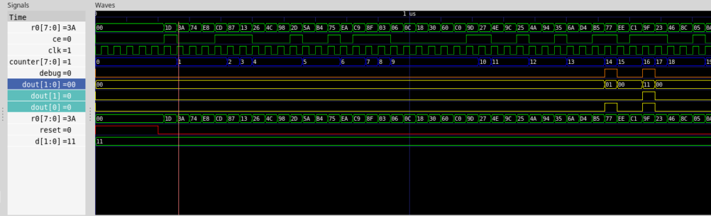
Let’s have a look at a MyHDL code snippet. This is a simple counter, that increments when ce is true (high). When it hits a certain value, the dout output is asserted to a specific value.

@block
def test_counter(clk, ce, reset, dout, debug):
    counter = Signal(modbv(0)[8:])
    d = Signal(intbv(3)[2:])

    @always_seq(clk.posedge, reset)
    def worker():
        if ce:
            counter.next = counter + 1

    @always_comb
    def assign():
        if counter == 14:
            dout.next = 1
            debug.next = 1
        elif counter == 16:
            debug.next = 1
            dout.next = 3
        else:
            debug.next = 0
            dout.next = 0

    return instances()

When we run a simple test bench which provides a clock signal clk, and some pseudo random assertion of the ce pin, we get this:

Waveform of simulation

Now, how do we pass this simple logic on to yosys for synthesis?

Pyosys python wrapper

The pyosys module is a generated python wrapper, covering almost all functionality from the RTLIL yosys API. In short, it allows us to instanciate a design and hardware modules and add hardware primitives. It’s like wiring up 74xx TTL logic chips, but the abstract and virtual way.

Means, we don’t have to create Verilog or VHDL from Python and run it through the classic yosys passes, we can emit synthesizeable structures directly from the self-parsing HDL.

Way to synthesis

Now, how do we get to synthesizeable hardware, and how can we control it?

We do have a signal representation after running the analysis routines of MyHDL. Like we used to convert to the desired transfer language, we convert to a design, like:

design = yshelper.Design("test_counter")
a = test_counter(clk, ce, reset, dout, debug)
a.convert("verilog")
a.convert("yosys_module", design, name="top", trace=True)
design.display_rtl() # Show dot graph

The yosys specific convert function, as of now, calls the pyosys interface to populate a design with logic and translates the pre-analysed MyHDL signals into yosys Wire objects and Signals that are finally needed to create the fully functional chain of the logic zoo. The powerful ‘dot’ output allows us to look at what’s being created from the above counter example (right click on image and choose ‘view’ to see it in full size):

Schematic of synthesis, first output stage

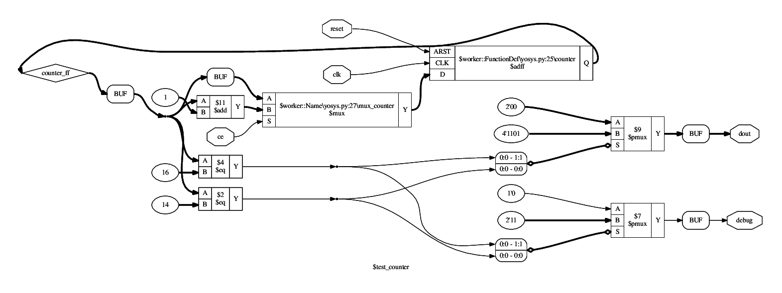
You might recognize the primitives from the hardware description. A compare node if counter == 14 translates directly to the $eq primitive with ID $2. A Data flip flop ($dff) however is generated somewhat implicit by the @always_seq decorator from the output of a multiplexer. And note: This $dff is only emitted, because we have declared the reset signal as synchronous from the top level definition. Otherwise, a specific asynchronous reset $adff would be instanciated.

The multiplexers finally are those nasty omnipresent elements that route signals or represent decisions made upon a state variable, etc.

You can see a $mux instanciated for the reset circuit of the worker() function, appended to another $mux taking the decision for the ce pin whether to keep the counter at its present value or whether to increment it ($11). The $pmux units are parallel editions that cover multiple cases of an input signal. Together with the $eq elements, they actually convert well to a lookup table — the actual basic hardware element of the FPGA.

Hierarchy

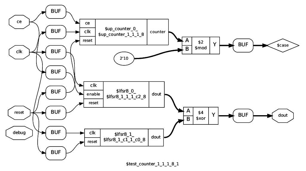
The standard VHDL/Verilog conversion flattens out the entire hierarchy before conversion. This approach avoids this by maintaining a wiring map between current module implementation and the calling parent. Since @block implementations are considered smart and can have arbitrary types of parameters (not just signals), this is tricky: We can not just blindly instance a cell for a module and wire everything up later, as it might be incompatible. So we determine a priori by a ‘signature key’ if a @block instance is compatible to a previous instance of the same implementation.

All unique module keys are thus causing inference of the implementation as a user defined cell. The above dot schematic displays the top level module, instancing a counter and two LFSR8 cells with different startup value and dynamic/static enable.

Black boxes

When instancing black box modules or cells directly from MyHDL, you had to create a wrapper for it, using the ugly vhdl_code or verilog_code attribute hacks. This can be a very tedious process, when you have to infer vendor provided cells. You could also direct this job to the yosys mapper. The following snippet demonstrates an implementation of a black box: the inst instance adds the simulation for this black box, however, the simulation is not synthesized, instead, the @synthesis implementation is applied during synthesis. Note that this can be conditional upon the specified USE_CE in this example.

@blackbox
def MY_BLACKBOX(a, b, USE_CE = False):
    "Blackbox description"
    inst = simulate_MY_BLACKBOX(a, b)

    @synthesis(yshelper.yosys)
    def implementation(module, interface):
        name = interface.name
        c = module.addCell(yshelper.ID(name), \
            yshelper.ID("blackbox"))
        port_clk = interface.addWire(a.clk)
        c.setPort(yshelper.PID("CLK"), port_clk)

        if USE_CE:
            port_en = module.addSignal(None, 1)
            in_en = interface.addWire(a.ce)
            in_we = interface.addWire(a.we)
            and_inst = module.addAnd(yshelper.ID(name + "_ce"), \
                in_en, in_we, port_en)
        else:
            port_en = interface.addWire(a.we)

        c.setPort(yshelper.PID("EN"), port_en)

    return inst, implementation

This also allows to create very thin wrappers using wrapper factories for architecture specific black boxes. In particular, we can also use this mechanism for extended High Level Synthesis (HLS) constructs.

Verification

Now, how would we verify if the synthesized output from the MyHDL snippet works correctly? We could do that using yosys’ formal verification workflow (SymbiYosys), but MyHDL already provides some framework: Co-Simulation from within a python script against a known working reference, like a Verilog simulation.

These verification tests are run automatically upon checkin (continuous integration, see also docker container hackfin/myhdl_testing:yosys)

An overview of the verification methods are given inside the above binder. Note: the myhdl_testing:yosys container is not up to date and is currently used for a first stage container build only.

Functionality embedded in the container:

  • Functional MyHDL simulation of the unit under test with random stimulation
  • Generation of Verilog code of the synthesized result
  • Comparison of the MyHDL model output against the Verilog simulation output by the cycle-synchronous Co-Simulation functionality of MyHDL

There are some advantages to this approach:

  • We can verify the basic correctness of direct Python HDL to yosys synthesis (provided that we trust yosys and our simulator tools)
  • We can match against a known good reference of a Verilog simulator (icarus verilog) by emitting Verilog code via MyHDL
  • Likewise, we can also verify against emitted VHDL code (currently not enabled)

Synthesis for target hardware (ECP5 Versa)

Currently, only a few primitives are supported to get a design synthesized for the Lattice ECP5 architecture, in particular the Versa ECP5 development kit. The following instructions are specific to a Linux docker environment.

First, connect the board to your PC and make sure the permissions are set to access the USB device. Then start the docker container locally as follows:

docker run -it --rm --device=/dev/bus/usb -p 8888:8888 hackfin/myhdl_testing:jupyosys jupyter notebook --ip 0.0.0.0 --no-browser

Then navigate to this link (you will have to enter the token printed out on the console after starting the container):

http://127.0.0.1:8888/notebooks/src/myhdl/myhdl-yosys/example/ipynb/index.ipynb

Then you can synthesize, map, run PnR and download to the target in one go, see the ECP5 specific examples in the playground.

Note: when reconnecting the FPGA board to Power or USB, it may be necessary to restart the container.

Status, further development

MyHDL main development has turned out to have some more serious issues:

  • Numerous bugs and piling up pull requests
  • Architectural issues (AST parsing versus execution/generation), problematic internals for hierarchy preservation
  • Slow execution for complex hierarchies
  • No closed source modules feasible

From more experiments with a different approach, the roadmap has become clearer such that all yosys related direct synthesis support is migrated to the new ‘v2we’ kernel which provides some MyHDL emulation. For the time being, the strategy is to go back to VHDL transfer and verification using GHDL to make sure the concept is sound and robust. Link to prototype examples:

https://github.com/hackfin/myhdl.v2we

Posted on

MaSoCist support of OpenSource synthesis for ECP5

Find the a (currently unstable) development branch here:

https://github.com/hackfin/MaSoCist/tree/ghdlsynth_release

NOTE: In process of upgrading to ghdl v1.0 synthesis. The build system is currently not functional. Use the self extracting script from the Instructions (2) below for a frozen working configuration.

Configurations that work (from those appearing when you run ‘make which’ in the masocist top dir):

  • *-zpu-ghdlsynth: ZPUng setup with ‘beatrix’ configuration.
  • *-pyrv32-ghdlsynth: RISC-V 32 bit basic configuration, proof of concept only, not fully functional as SoC in synthesis (as of now)
    Note: You need to explicitely install the rv32 toolchain (inside the docker container) for this config:
    sudo apt-get install riscv32-binutils riscv32-gcc riscv32-newlib-libc

Instructions

This can be done online in a browser, if you don’t run Linux, see also https://section5.ch/index.php/2019/10/24/risc-v-in-the-loop/.

Note: Since this setup depends on external packages, there is no guarantee it will build smoothly.

  1. Run docker container with exported USB devices (if you want to program the plugged in board right away):
    docker run -it --device=/dev/bus/usb hackfin/masocist:synth
  2. Pull synthesis self-extracting build script:
    wget https://section5.ch/downloads/masocist-synth_sfx.sh && sh masocist-synth_sfx.sh
  3. Pull packages and build:
    make all
  4. Configure platform:
    cd src/vhdl/masocist-opensource;
    make versa_ecp5-zpu-ghdlsynth
  5. Build for synthesis:
    make clean sw syn
  6. When successful, you’ll end up with a $(PLATFORM).SVF file in syn/.
  7. See next paragraph on how to program the board (this procedure will be simplified)

Supported boards

Currently, the following ECP5 based boards are supported/under scrutiny:

Programming with on board FT2232H JTAG interface:

Note that programming will only work when the container is run/started after plugging in the board.

To program the FPGA SRAM on the board with the produced SVF file:

  1. Make sure board is connected via USB and powered up.
  2. You may need to restart the container from above:
    docker start -i <id>
    where ‘id’ is the container id of the above stopped container (retrieve from shell history or with docker ps -a)
  3. Install openocd:
    sudo apt-get install openocd
  4. Make sure board is connected via USB and powered up, then run, inside $(MASOCIST)/syn:
    make download OPENOCD="sudo openocd"
  5. If you see a lot scrolling by, board programming tends to be successful (interface was recognized). You can ignore errors like:
    Error: tdo check error at line 26780
    as they are due to the changed USERCODE.
  6. You should see the segment display on the board ‘spinning’. Also, you can talk to the SoC through the UART at 115200, 8N1, for example using minicom:
    minicom -o -D /dev/ttyUSB1
    The output upon booting of the SoC should be:
Probing flash…
Flash Type: m25p128         
Booting beatrix HW rev: 04 @25 MHZ
------------- test shell -------------                                          
--        SoC for Versa ECP5        --                                          
            arch: ZPUng                                                          
--  (c) 2012-2020  www.section5.ch  --                                          
--     type 'h' for help            --                                          
 

Quirks

Short summary on what works in particular and what does not:

Ram inference

RAM inference is currently problematic and needs to be investigated further. TODO:

  • Make synthesis recognize more variants of RAM with init values
  • Implement dual process true dual port RAM
  • Fully eliminate Verilog RAM wrapper workarounds

FSM optimization

Some FSM seem to optimize away in yosys. Needs to be investigated if it’s a VHDL synthesis or internal Yosys issue.

Vendor primitives

Vendor specific Black Box primitives will no longer have to be wrapped starting with new ghdl-1.0 releases (Container namehackfin/masocist:synth-1.0). However, for the time being you might want to visit:

https://github.com/ghdl/ghdl-yosys-plugin/issues/46

So far tested primitives within MaSoCist:

  • JTAGG: Test access port to ZPUng and pyrv32 for JTAG debugging or automated in circuit emulation hardware tests.
  • EHXPLLL: PLL primitive for clock frequency conversion
  • USRMCLK: Access to SPI master clock on ECP5

Not working

  • System Interrupt Controller (CONFIG_SIC) is currently not supported: #1140
    Fixed. Make sure to install the up to date debian GHDL packages when reusing an old container:
    sudo apt-get update; sudo apt-get install ghdl ghdl-libs
    You also have to rebuild the ghdl.so module in src/ghdl-yosys-plugin:
    make clean all; sudo make install
  • FLiX DSP and JPEG core unsupported (due to true dual port RAM issues)
  • Under scrutiny: pktfifo (CONFIG_MAC) problematic (TDP BRAM issues)
  • Post map simulation does not work with DP16KD primitives, due to missing ‘whitebox’ model, see also #32. You will have to separately use the supplied vendor model from the Diamond libraries.
Posted on Leave a comment

SCADA/HMI-Optimierung mit SVG und netpp

Die Erstellung einer klassischen Prozessansicht in der Automation sieht im Arbeitsprozess aus, wie folgt:

  • Registertabellen aus der modbus-Sektion abtippen und mit einer Widget-ID der HMI-Anzeige verbinden
  • Zustand eines Elements, z.B. Ventil innerhalb der Prozesskette in verschiedene Bitmaps codieren, z.B.:
    • 0 : Initialisierung des Ventils (Zustand unbekannt)
    • 1: Ventil offen
    • 2: Ventil zu
    • 3: Fehler
  • In der Abfrage wird laufend der Zustandswert aus dem Register ausgelesen und die entsprechende Bitmap an der Stelle der Prozessübersicht gezeichnet.

Mit dem weitverbreiteten und gut standardisierten Vektorformat SVG geht das eleganter:

  • Einem Element in der Grafik einen Namen geben
  • Dem Namen über eine Datenbank allenfalls eine Registeradresse zuweisen
  • Die ganze Prozedur der Aktualisierung einem Framework überlassen

Diverse SCADA-Lösungen setzen teils auf Browser-Technologien auf, da sie von Haus aus Unterstützung für das SVG-Format mitbringen. Diese benötigen typischerweise einen embedded Webserver, der die regelmässige Abholung der Registerdaten in der ganzen Prozesskette organisiert und für den Browser entsprechend der bereitstehenden REST-APIs aufbereitet. Es gibt aber auch kompaktere Lösungen, die Support für SVG mitbringen, wie die OpenSource-Lösung pvbrowser von Rainer Lehrig.

Hier wird insbesondere die Integration in den pvhub-Prozesskontrolle-Server mit dem netpp-Subsystem beschrieben. Dabei arbeitet man allerdings in der anderen Richtung, d.h. die Netpp-Property-Namen dienen als Namen (‘id’) für das zugeordnete SVG-Element und die zentrale Datenbank fällt weg.

Anleitung

Am Beispiel eines Zwei-Wege-Verteilers soll hier eine kurze Anleitung gegeben werden, wie der Zustand eines Elements elegant in die Grafik überführt wird. Dazu benutzen wir das mächtige Opensource-Tool Inkscape, siehe auch Download. Der Zustand des ZWV ist in einem Register-Bitfeld codiert, welches durch ein netpp-Property vom Typ MODE beschrieben wird. Dieses MODE-Property enthält die möglichen Zustände als Kinder, z.B:

Type : Mode [RWV]
Child: (m) [200000d5] 'LR_PUR'
Child: (m) [200000d6] 'L_PUR'
Child: (m) [200000d7] 'R_PUR'
Child: (m) [200000d8] 'OFF'
Child: (m) [200000d9] 'LR_ALARM'
Child: (m) [200000da] 'L_ON'
Child: (m) [200000db] 'R_ON'
Child: (m) [200000dc] 'L_ERR'
Child: (m) [200000dd] 'R_ERR'

Zeichnen Sie dabei für jeden Zustand eine einzelne Grafik. Arbeiten Sie dabei am besten mit Hilfe von Layern, dass die einzelnen Grafiken direkt übereinander zu liegen kommen. Das erspart nachträgliche und aufwendigere Translationen.

Gruppieren Sie anschliessend jede Grafik per Zustand einzeln. Danach teilen Sie dieser Gruppe einen eindeutigen Namen zu, und zwar den vollen hierarchischen Namen des netpp-Property-Zustands, z.B.

Monitor.ProcessingUnit.Crumbler[0].TwoWayDistState.L_ON

Benutzen Sie dazu allenfalls den XML-Editor in Inkscape:

Die Einzelgrafiken werden schlussendlich in einen Layer aufeinander kopiert. Schliesslich müssen alle Zustandsgrafiken noch ein letztes Mal mit Ctrl-G gruppiert werden, dieser Gruppe weisen Sie dann den Namen des Property zu:

Monitor.ProcessingUnit.Crumbler[0].TwoWayDistState

Für eine einfache Umsetzung reicht zunächst, die SVG-Grafik mit dem Rapid-Prototying-Tool pvdevelop (Teil der pvbrowser-Software) einzubinden und ihm die Objekt-ID der gesammelten Monitor-Hierarchie zu übergeben, also: “_#Monitor”. Die Prefix ‘_’ sorgt für die Property-Abfrage, das ‘#’ markiert ein Property das im lokalen Cache gepuffert wird (was eine ineffiziente Abfrage vieler Einzel-Properties optimiert).

Der Ablauf der Prozessanzeige sieht dann aus wie folgt:

  • Das Monitor-Property wird einmal pro Intervall abgefragt
  • Alle Kinder davon werden “besucht” und deren Zustand ermittelt, der Name des Zustands wird dann verwendet, um das entsprechende Objekt in der Grafik sichtbar zu machen. Dabei werden a priori alle Zustandsgrafiken unsichtbar gemacht und nur die Grafik zum aktiven Zustand wird sichtbar.

Für andere Arten von Eigenschaften nimmt das Framework eine Standard-Anzeige vor, diese ist auch insbesondere vom zugewiesenen Namen des Property abhängig. Dabei werden normalerweise einfache Primitiven (Polygone oder Kreise, etc.) in der Zeichnung verwendet, deren Füllfarbe einfach ausgetauscht wird. Im folgendenden eine kurze Auflistung:

  • BOOL: Wert True (1) wird durch grüne Füllfarbe markiert, 0 mit rot
  • INT:
    • Name: Rotation, Wert von 0..359: Grafik wird entsprechend rotiert
    • Name: Position, enthält Min und Max Kinder: Grafik wird um den Wert in X verschoben. Die effektive Positionierung errechnet sich dabei aus der Skalierung des Parent-Property-Objekts. Falls keine Kinder angegeben sind, ist der Wert eine Prozentangabe von 0..100.
    • Name: Fill, von 0..100, sofern keine Min oder Max Kinder angegeben, definiert den Füllstand eines Tanks. Die Grafik des Tanks muss dabei die entsprechenden Dimensionen einhalten, die Skalierung findet via das übergeordnete Gruppierungselement statt.

Fazit

Für den Integrator wird die Erstellung einer HMI-Anzeige somit weniger aufwendig, vorausgesetzt die Datenbank der einzelnen Geräte steht bereits oder ist durch bereits netpp-fähige Geräte abgedeckt.

Sie können somit die Grafik und die nötigen Animationen selbst erstellen, und anhand der vorliegenden Property-Referenz einzeln zuweisen. Allfällige Anpassungen der SVG-Grafik sind dabei meist unproblematisch.

Schliesslich können Sie die Anzeige wie gewohnt per pvbrowser aufrufen und sehen entsprechend die Zustände der Elemente in der so animierten SVG-Grafik.

Monitor Prozesskontrolle

Ein weiterer Vorteil: Die SVG-Grafik benötigt gegenüber der Pixelgrafik weniger Speicherplatz. Somit kann es auch auf limitierten netpp-Geräten im SPI-Flash untergebracht und per Property Monitor.SVGImage abgefragt werden.

Stolperfallen/Tips

Bei der Erstellung der SVG-Grafiken gilt es, einiges zu beachten:

  • Zeichnen Sie die Elemente am besten von Anfang an masstabsgetreu, d.h. nutzen Sie mm als Einheit. Typischerweise werden die HMI-Anzeigen so abgestimmt, dass das Element in der richtigen Grösse gezeichnet wird
  • Gruppieren Sie erst am Schluss, bevor Sie den Namen zuweisen. Bei Gruppierungsaktionen können Namen verlorengehen.
  • Nutzen Sie auch den Objects-Editor (Menü: Object->Objects) zur Kontrolle der Hierarchien und Sichtbarkeit.
  • Sie können zusätzlich zur ID auch ein ‘Label’ vergeben, was denselben Namen haben kann, aber nicht eindeutig vorkommen muss. Das erleichtert das Auffinden im Objects-Editor.
  • Achten Sie darauf, dass bei rotierenden Animationen der Nullpunkt des Objekts als Rotationszentrum gilt. Die Position kann dann durch eine übergeordnete Gruppe definiert werden. Kennzeichnen Sie ansonsten den Rotationsmittelpunkt durch ein Kreuz, o.ä.